
TM 5-3805-298-23-2
0180
REMOVAL CONTINUED
NOTE
Tag and mark tubes to aid installation.
Plug or cap tube ends and open ports.
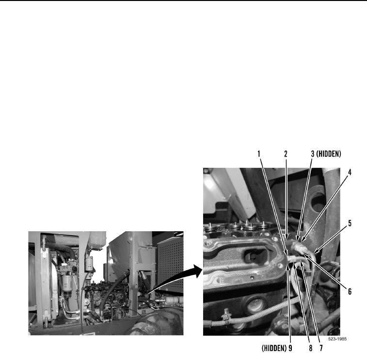
3. Loosen tube nut (Figure 2, Item 6) and remove tube (Figure 2, Item 5) from fitting (Figure 2, Item 4).
4. Remove fitting (Figure 2, Item 4) and O-ring (Figure 2, Item 3) from cylinder head (Figure 2, Item 2). Discard
fitting and O-ring.
5. Loosen tube nut (Figure 2, Item 8) and remove tube (Figure 2, Item 7) from fitting (Figure 2, Item 1).
6. Remove fitting (Figure 2, Item 1) and sealing washer (Figure 2, Item 9) from cylinder head (Figure 2, Item 2).
Discard sealing washer.
Figure 2. Tubes and Fittings.
0180