
TM 5-3805-298-23-2
0186
ADJUSTMENT CONTINUED
4. Using 1/2" drive ratchet and crankshaft turning tool, rotate crankshaft until inlet valves are fully open for
specified cylinder.
NOTE
Rotating crankshaft until correct inlet valves are fully open refers to a rocker shaft that has
fully compressed valve spring, fully opening valve.
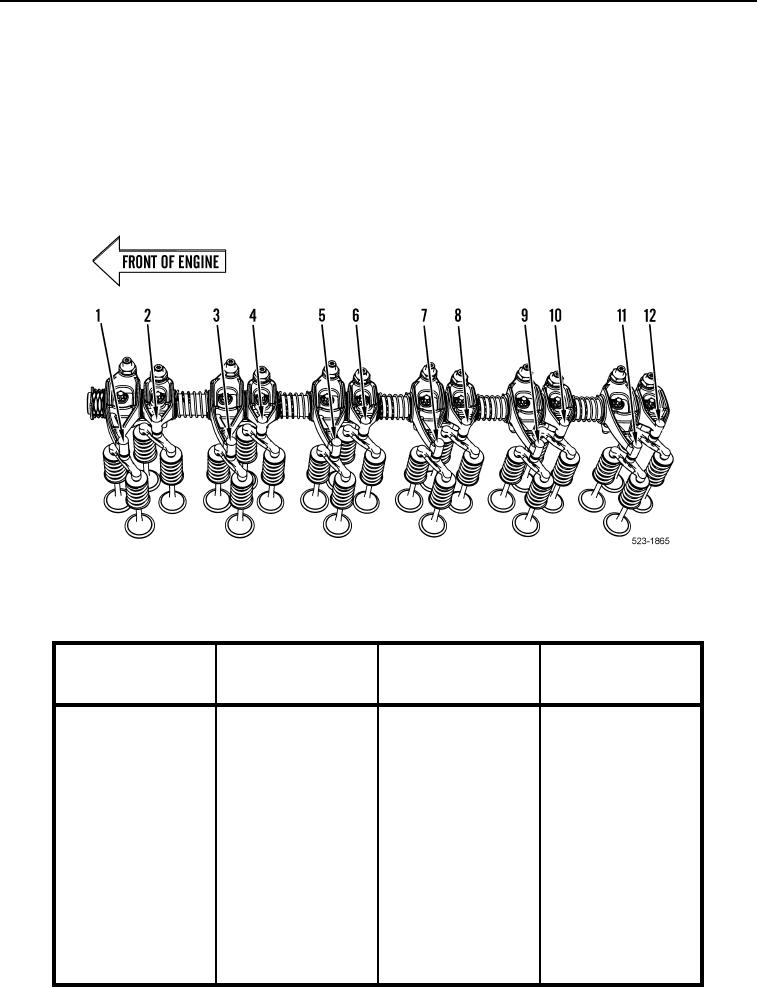
5. Set valve lash for corresponding inlet valves and exhaust valves (Table 1) and (Figure 5, Items 1 through 12).
Figure 5. Inlet/Exhaust Valve Arrangement.
0186
Table 1. Valve Lash Sequence.
0186
Rotate Crankshaft
Cylinder Number
Inlet Valves
Exhaust Valves
0186
Until Inlet Valves
0186
0186
Are Fully Open
0186
5
1
1
2
1
2
3
4
3
3
5
6
9
4
7
8
11
5
9
10
7
6
11
12