
TM 5-3805-298-23-2
0186
ADJUSTMENT CONTINUED
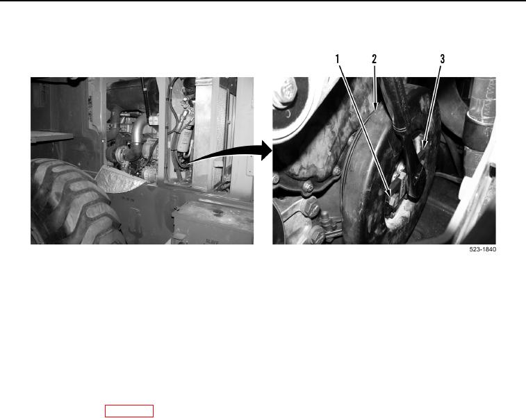
Figure 7. Crankshaft Turning Tool.
0186
11. Remove two bolts (Figure 7, Item 1) and engine turning tool (Figure 7, Item 3) from crankshaft damper
(Figure 7, Item 2).
12. Install two bolts (Figure 7, Item 1) on crankshaft damper (Figure 7, Item 2).
13. Install drive belt (WP 0239).
END OF TASK
FOLLOW-ON TASKS
000186
1. Install valve cover (WP 0187).
2. Verify correct operation of machine (TM 5-3805-298-10).
END OF TASK
END OF WORK PACKAGE
0186-9/(10 blank)