
TM 5-3805-298-23-2
0198
INSTALLATION CONTINUED
CAUTION
If installing used valve links, ensure valve links are installed in original location and
orientation on cylinder head. Do not interchange location or orientation of valve links.
Failure to follow this caution may cause premature wear.
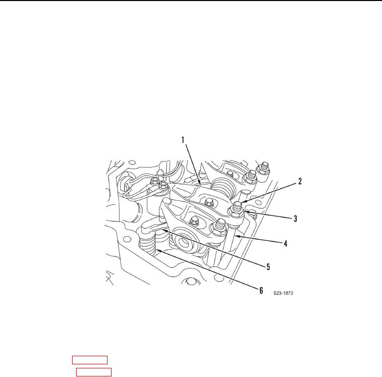
10. Install two valve links (Figure 10, Item 5) on four valve springs (Figure 10, Item 6).
11. Ensure cups of pushrods (Figure 10, Item 4) are seated on ball of valve lifters. Position rocker arms (Figure 10,
Item 1) so ball of adjuster (Figure 10, Item 2) is in cup of pushrod. Finger tighten adjuster nut (Figure 10,
Item 3).
Figure 10. Valve Bridge Replacement.
0198
END OF TASK
FOLLOW-ON TASKS
000198
1. Adjust valve lash (WP 0186).
2. Install valve cover (WP 0187).
3. If fuel injector was replaced, load trim files to ECM on new fuel injector (WP 0011).
4. Verify correct operation of machine (TM 5-3805-298-10).
END OF TASK
END OF WORK PACKAGE
0198-11/(12 blank)