
TM 5-3805-298-23-2
0199
REMOVAL CONTINUED
NOTE
Tag wiring harness connectors and note wiring harness routing to aid installation.
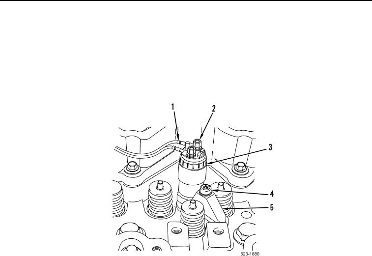
4. Remove 12 nuts (Figure 2, Item 2) and electrical terminals (Figure 2, Item 1) from six fuel injectors
(Figure 2, Item 3).
5. Remove six bolts (Figure 2, Item 4) from six clamps (Figure 2, Item 5). Discard machine bolts.
Figure 2. Fuel Injector Electrical Connection Replacement.
0199