
TM 5-3805-298-23-2
0203
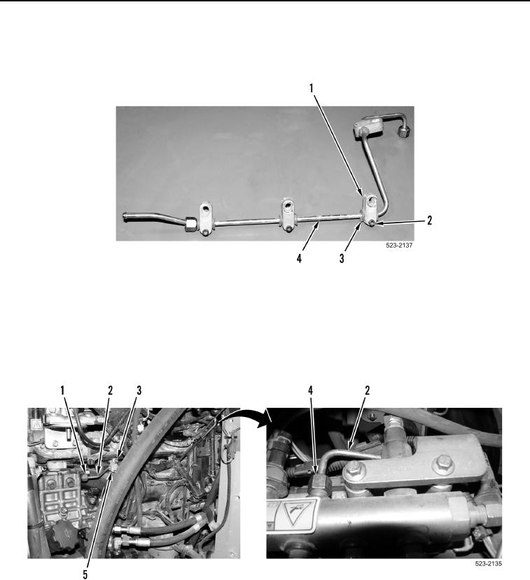
INSTALLATION CONTINUED
10. Install four isolators (Figure 18, Item 3), clamps (Figure 18, Item 1), and bolts (Figure 18, Item 2) on new fuel
line (Figure 18, Item 4).
Figure 18. Fuel Line Clamps.
0203
11. Position fuel line (Figure 19, Item 2) and four clamps (Figure 19, Item 5) on machine.
12. Install two tube nuts (Figure 19, Items 1 and 4) and fuel line (Figure 19, Item 2) on machine. Tighten tube nuts
to 22 lb-ft (30 Nm).
13. Install four bolts (Figure 19, Item 3) on four clamps (Figure 19, Item 5).
Figure 19. Fuel Line.
0203