
TM 5-3805-298-23-2
0203
INSTALLATION CONTINUED
NOTE
Ensure timing marks on gears as noted in removal are in alignment.
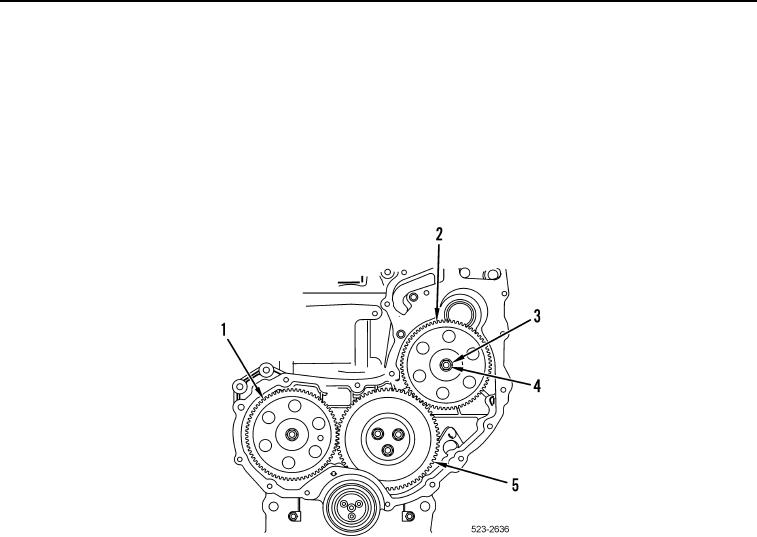
22. Install fuel injection pump gear (Figure 24, Item 2), new lockwasher (Figure 24, Item 4) and nut (Figure 24,
Item 3) on engine. Ensure timing marks on camshaft gear (Figure 24, Item 1), idler gear (Figure 24, Item 5),
and fuel injection pump gear (Figure 24, Item 2) are in alignment and mesh is correct.
23. Tighten nut (Figure 24, Item 3) to 20 lb-ft (27.11 Nm).
Figure 24. Fuel Injection Pump Gear.
0203