
TM 5-3805-298-23-2
0203
INSTALLATION CONTINUED
NOTE
Steps 1922 disassemble tool.
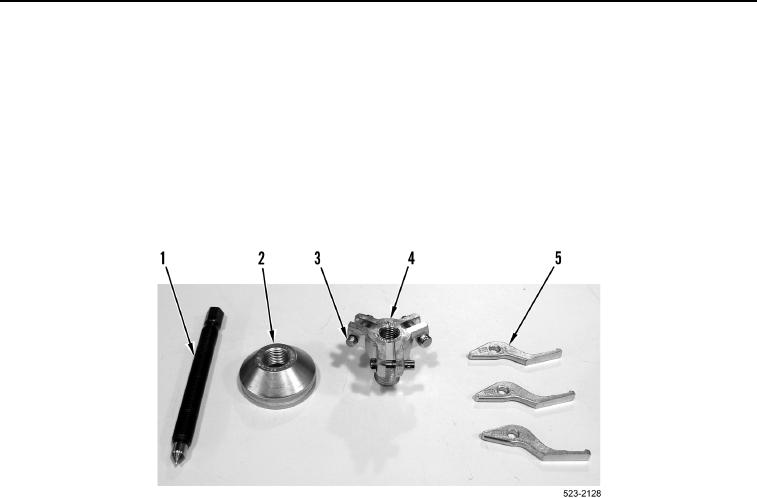
24. Remove cone (Figure 25, Item 2) from puller body (Figure 25, Item 4).
25. Remove three pins (Figure 25, Item 3) and jaws (Figure 25, Item 5) from puller body (Figure 25, Item 4).
26. Install three pins (Figure 25, Item 3) on puller body (Figure 25, Item 4).
27. Remove shaft (Figure 25, Item 1) from puller body (Figure 25, Item 4).
Figure 25. Puller Assembly.
0203