
TM 5-3805-298-23-2
0225
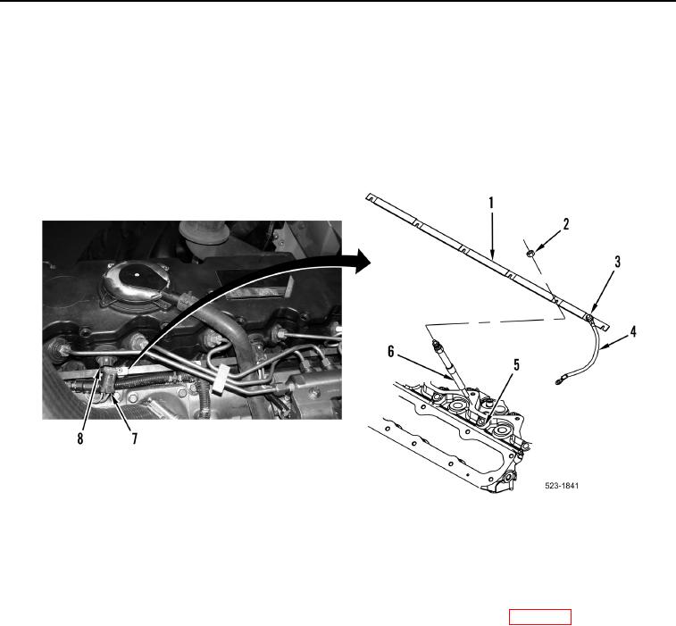
REMOVAL CONTINUED
2. Remove nut (Figure 2, Item 3) and cable (Figure 2, Item 4) from bus bar. (Figure 2, Item 1).
3. Disconnect injector 1 and 2 harness connector (Figure 2, Item 8) from engine control harness connector
(Figure 2, Item 7).
4. Remove six nuts (Figure 2, Item 2) securing bus bar (Figure 2, Item 1) to six glow plugs (Figure 2, Item 6).
5. Remove bus bar (Figure 2, Item 1) from glow plugs (Figure 2, Item 6).
6. Remove six glow plugs (Figure 2, Item 6) from cylinder head (Figure 2, Item 5). Discard glow plugs.
Figure 2. Glow Plugs.
0225
END OF TASK
CLEANING AND INSPECTION
000225
Clean and inspect all components IAW Mechanical General Maintenance Instructions (WP 0172).
END OF TASK