
TM 5-3805-298-23-2
0226
REMOVAL CONTINUED
000226
NOTE
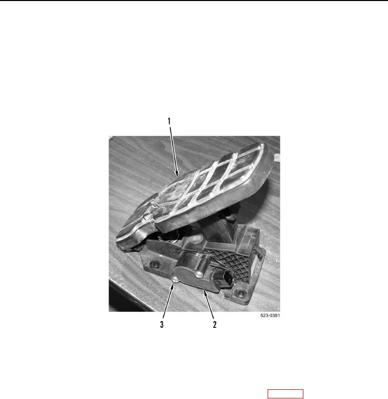
Note orientation of throttle position sensor to aid installation.
There is a small amount of tension against throttle position sensor. It will move slightly
when bolts are removed.
7. Remove two bolts (Figure 4, Item 3) and throttle position sensor (Figure 4, Item 2) from governor pedal
(Figure 4, Item 1).
Figure 4. Throttle Position Sensor.
0226
END OF TASK
CLEANING AND INSPECTION
000226
Clean and inspect all parts IAW Mechanical General Maintenance Instructions (WP 0172).
END OF TASK