
TM 5-3805-298-23-2
0226
REMOVAL
000226
WARNING
Ensure that battery disconnect switch is set to OFF before performing this task. Failure to
follow this warning could result in injury or death to personnel.
NOTE
Tag and mark all connections to aid installation.
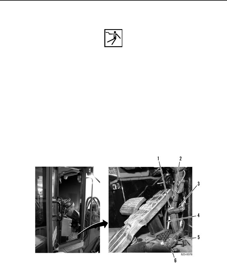
1. Disconnect throttle position sensor jumper harness connector (Figure 1, Item 1) from main cab wiring harness
connector (Figure 1, Item 3).
2. Disconnect throttle position sensor jumper harness connector (Figure 1, Item 5) from throttle position sensor
(Figure 1, Item 6).
NOTE
Note location and number of tiedown straps to aid installation.
3. Remove tiedown straps (Figure 1, Item 2) and throttle position sensor jumper harness (Figure 1, Item 4) from
machine. Discard tiedown straps.
Figure 1. Throttle Position Sensor Jumper Harness.
0226