
TM 5-3805-298-23-2
0226
INSTALLATION
000226
NOTE
Install governor position sensor as noted during removal.
It may be necessary to turn throttle position sensor slightly to allow bolts to align with
governor pedal.
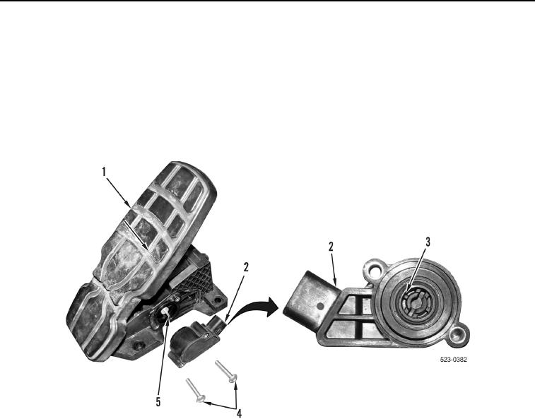
1. Align slot (Figure 5, Item 3) on throttle position sensor (Figure 5, Item 2) with tab (Figure 5, Item 5) and install
throttle position sensor (Figure 5, Item 2) and two bolts (Figure 5, Item 4) on governor pedal (Figure 5, Item 1).
Figure 5. Throttle Position Sensor.
0226