
4
TM 5-3805-298-23-4
FIELD MAINTENANCE
-
DEFROSTER RELAY AND SWITCH REPLACEMENT
03
64
Removal, Cleaning and Inspection, Installation
INITIAL SETUP
References
Tools and Special Tools
0
0
Tool Kit, General Mechanic's
WP 0174
0
(WP 0431, Item 162)
0
Equipment Conditions
0
Socket Driver, Torx, 3/8" Drive, T-15
Machine parked (TM 5-3805-298-10)
(WP 0431, Item 122)
0
0
Socket Driver, Torx, 3/8" Drive, T-30
Estimated Time to Complete
0
(WP 0431, Item 125)
0
0.8 Hr
0
Materials/Parts
0
Rag, Wiping (WP 0430, Item 27)
0
Tag, Marker (WP 0430, Item 35)
0
REMOVAL
000364
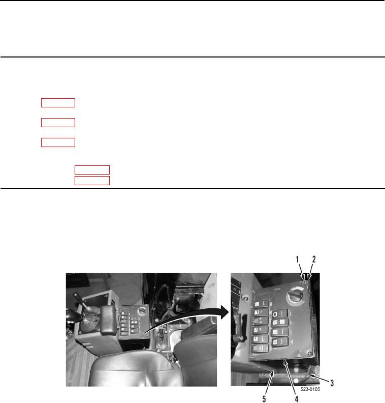
1. Remove four bolts (Figure 1, Item 1) and washers (Figure 1, Item 2) from switch panel (Figure 1, Item 4).
2. Insert slack from cable (Figure 1, Item 3) and position switch panel (Figure 1, Item 4) aside from console
(Figure 1, Item 5).
Figure 1. Switch Panel.
0364