
TM 5-3805-298-23-4
0364
REMOVAL CONTINUED
NOTE
Tag and mark wiring harness connectors and note wiring harness routing to aid
installation.
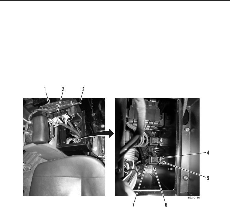
3. Disconnect lower cab wiring harness connector (Figure 2, Item 2), from defrost switch(Figure 2, Item 1).
4. Remove defrost switch (Figure 2, Item 1) from switch panel (Figure 2, Item 3).
5. Remove bolt (Figure 2, Item 4) and washer (Figure 2, Item 5) from defroster relay (Figure 2, Item 6).
6. Disconnect lower cab wiring harness connector (Figure 2, Item 7) from defroster relay (Figure 2, Item 6).
7. Remove defroster relay (Figure 2, Item 6) from machine.
Figure 2. Defroster Relay.
0364
END OF TASK
CLEANING AND INSPECTION
000364
Clean and inspect all parts IAW Electrical General Maintenance Instructions (WP 0174).
END OF TASK