
TM 5-3805-298-23-4
0383
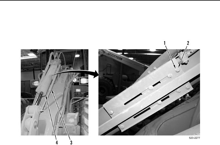
REMOVAL CONTINUED
4. Remove four bolts (Figure 3, Item 2) and washers (Figure 3, Item 1) and position sensor (Figure 3, Item 3) from
bucket tilt cylinder (Figure 3, Item 4).
5. Set position sensor (Figure 3, Item 3) aside.
Figure 3. Position Sensor.
0383