• Home
  • Download PDF
  • Order CD-ROM
  • Order in Print
Figure 3. Position Sensor.
Figure 5. Tube Nut, Hose, and O-ring.

Field Maintenance Manual For 924H Wheel Loader -4 Page Navigation
  202    203    204    205    206  207  208    209    210    211    212  
img
.
TM 5-3805-298-23-4
0383
REMOVAL CONTINUED
NOTE
Note orientation of clips to aid installation.
Note hose routing to aid installation.
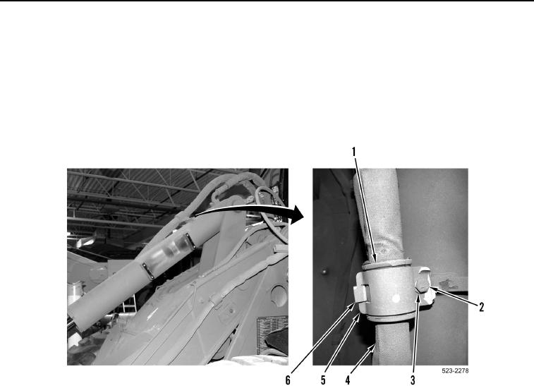
6. Remove bolt (Figure 4, Item 2), washer (Figure 4, Item 3), two clips (Figure 4, Items 5 and 6), and isolator
(Figure 4, Item 1) from hose (Figure 4, Item 4).
Figure 4. Clips and Isolator.
0383
0383-5


Privacy Statement
Press Release
Contact

© Copyright Integrated Publishing, Inc.. All Rights Reserved.