
TM 5-3805-298-23-4
0383
INSTALLATION CONTINUED
NOTE
Remove caps or plugs and install hose as noted during removal.
Use container to catch any fluid that may drain from hydraulic system. Dispose of fluid IAW
local policy and ordinances. Ensure all spills are cleaned up.
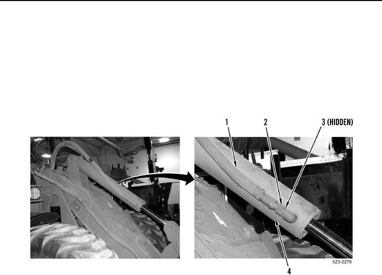
14. Install new O-ring (Figure 13, Item 3), hose (Figure 13, Item 1), and tube nut (Figure 13, Item 2) on bucket tilt
cylinder (Figure 13, Item 4).
Figure 13. Tube Nut, Hose, and O-ring.
0383