
TM 5-3805-298-23-4
0383
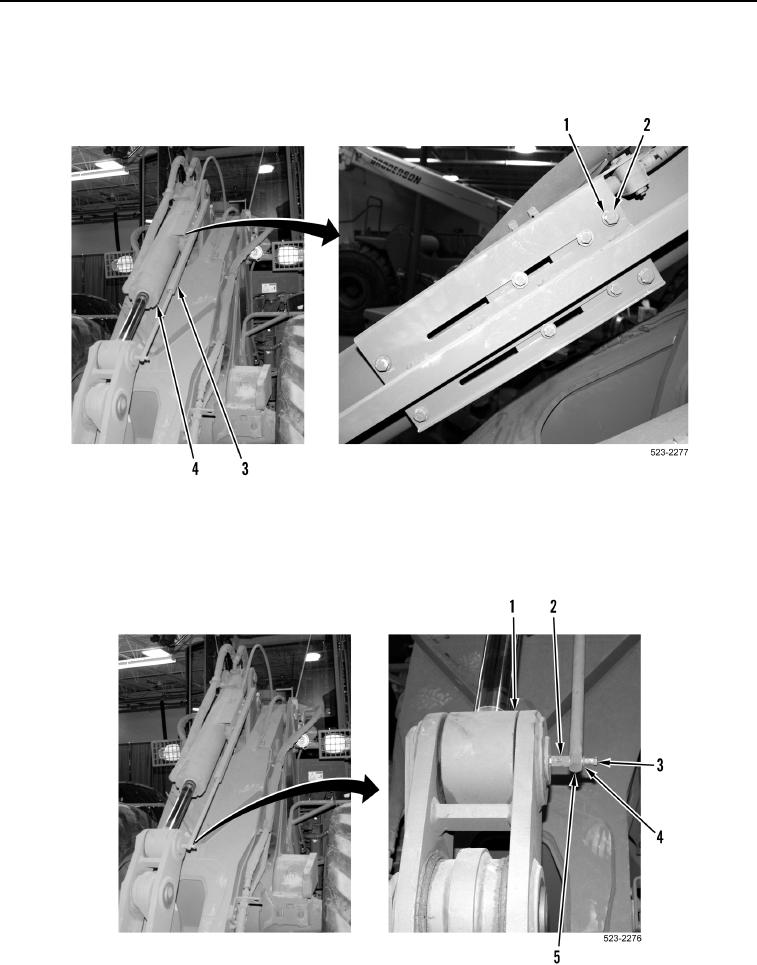
INSTALLATION CONTINUED
16. Install position sensor (Figure 15, Item 3), four washers (Figure 15, Item 1), and bolts (Figure 15, Item 2) on
bucket tilt cylinder (Figure 15, Item 4).
Figure 15. Position Sensor.
0383
17. Install shaft (Figure 16, Item 5), washer (Figure 16, Item 4), jam nut (Figure 16, Item 2) and bolt (Figure 16,
Item 3) on bucket tilt cylinder support (Figure 16, Item 1).
Figure 16. Position Sensor Shaft.
0383