
TM 5-3805-298-23-4
0384
REMOVAL CONTINUED
NOTE
Cap or plug hose end and fitting to protect against contamination.
Tag and mark hose and fitting and note hose routing to aid installation.
Use container to catch any fluid that may drain from hydraulic system. Dispose of fluid IAW
local policy and ordinances. Ensure all spills are cleaned up.
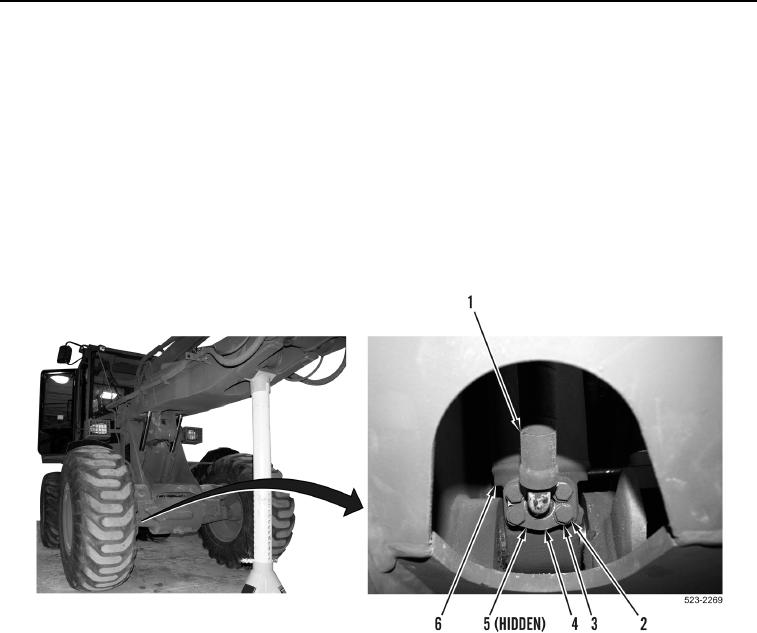
4. Position drain pan to catch fluid that drains from hose (Figure 2, Item 1) or cylinder (Figure 2, Item 6).
5. Remove four bolts (Figure 2, Item 2), washers (Figure 2, Item 3), hose (Figure 2, Item 1), two split flange
clamps (Figure 2, Item 4), and O-ring (Figure 2, Item 5) from bucket lift cylinder (Figure 2, Item 6). Discard
O-ring.
Figure 2. Hose, Split Flange Clamps, and O-ring.
0384