
TM 5-3805-298-23-4
0397
LEFT BATTERY BOX AND NATO SLAVE INSTALLATION CONTINUED
NOTE
Install cables, spacer and outer gasket as noted during removal.
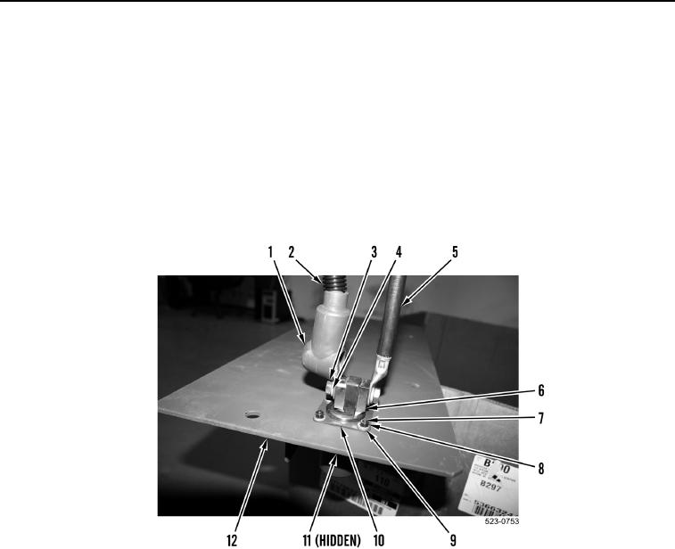
10. Install outer gasket (Figure 16, Item 11), NATO slave receptacle (Figure 16, Item 6), spacer
(Figure 16, Item 10), four bolts (Figure 16, Item 7), washers (Figure 16, Item 9), and nuts (Figure 16, Item 8) on
plate (Figure 16, Item 12).
11. Install NATO slave ground cable (Figure 16, Item 5), NATO slave positive cable (Figure 16, Item 2), two
washers (Figure 16, Item 4), and bolts (Figure 16, Item 3) on NATO slave receptacle (Figure 16, Item 6).
12. Position cable boot (Figure 16, Item 1) on NATO slave positive cable (Figure 16, Item 2).
Figure 16. NATO Slave Receptacle.
0397