
TM 5-3805-298-23-4
0408
REMOVAL CONTINUED
NOTE
Note cable routing to aid installation.
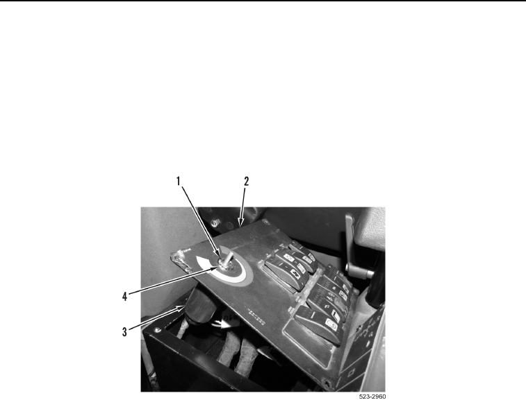
6. Remove nut (Figure 4, Item 1) and lockwasher (Figure 4, Item 5) from switch panel (Figure 4, Item 2). Discard
lockwasher.
7. Remove cab temperature control assembly (Figure 4, Item 4) from switch panel (Figure 4, Item 2).
8. Remove cab temperature control assembly (Figure 4, Item 4) and temperature control cable (Figure 4, Item 3)
from machine.
Figure 4. Cab Temperature Control.
0408
END OF TASK
CLEANING AND INSPECTION
000408
Clean and inspect all parts IAW Mechanical General Maintenance Instructions (WP 0172).
END OF TASK