• Home
  • Download PDF
  • Order CD-ROM
  • Order in Print
Figure 4. Cab Temperature Control.
Figure 6. Cab Temperature Control.

Field Maintenance Manual For 924H Wheel Loader -4 Page Navigation
  480    481    482    483    484  485  486    487    488    489    490  
img
.
TM 5-3805-298-23-4
0408
INSTALLATION
000408
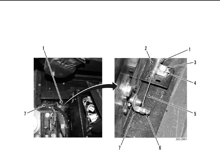
1. Install temperature control cable end (Figure 5, Item 5) and retainer clip (Figure 5, Item 6) on lever
(Figure 5, Item 7).
2. Install clamp (Figure 5, Item 2), new lockwasher (Figure 5, Item 4), and bolt (Figure 5, Item 3) on temperature
control cable (Figure 5, Item 1).
Figure 5. Cab Temperature Control Cable.
0408
0408-5


Privacy Statement
Press Release
Contact

© Copyright Integrated Publishing, Inc.. All Rights Reserved.