• Home
  • Download PDF
  • Order CD-ROM
  • Order in Print
Figure 5. Cab Temperature Control Cable.
Figure 7. Cab Temperature Control Knob.

Field Maintenance Manual For 924H Wheel Loader -4 Page Navigation
  481    482    483    484    485  486  487    488    489    490    491  
img
.
TM 5-3805-298-23-4
0408
INSTALLATION CONTINUED
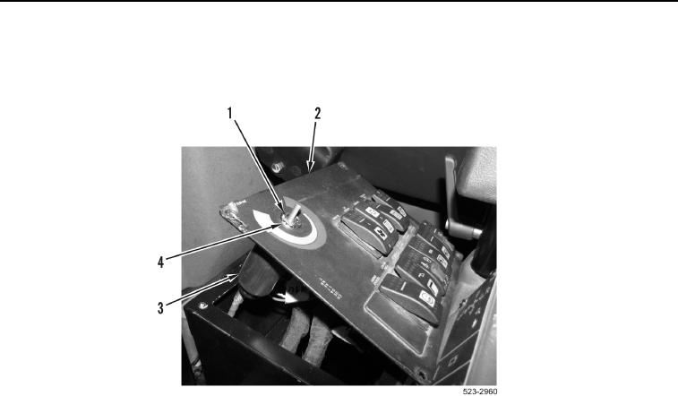
3. Install cab temperature control assembly (Figure 6, Item 3) on switch panel (Figure 6, Item 2).
4. Install new lockwasher (Figure 6, Item 4) and nut (Figure 6, Item 1) on switch panel (Figure 6, Item 2).
Figure 6. Cab Temperature Control.
0408
0408-6


Privacy Statement
Press Release
Contact

© Copyright Integrated Publishing, Inc.. All Rights Reserved.