Home
Download PDF
Order CD-ROM
Order in Print
Figure 6. Cab Temperature Control.
Figure 8. Switch Panel.
Field Maintenance Manual For 924H Wheel Loader -4
Page Navigation
482
483
484
485
486
487
488
489
490
491
492
TM
5-3805-298-23-4
0408
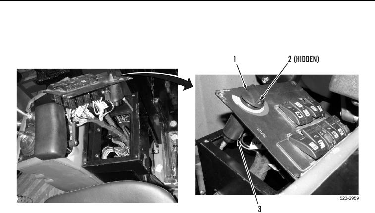
INSTALLATION
CONTINUED
5.
Install
knob
(Figure
7,
Item
1) on cab
temperature
control
assembly
(Figure
7,
Item
3)
and
tighten
screw
(Figure
7,
Item
2).
Figure 7.
Cab
Temperature
Control
Knob.
0408
0408-7