
TM 5-3805-298-23-4
0419
INSTALLATION
000419
NOTE
Remove caps or plugs and install hose as noted during removal.
1. Install new O-ring (Figure 6, Item 14), elbow fitting (Figure 6, Item 12), and tube nut (Figure 6, Item 13) on
auxiliary air conditioning condenser (Figure 6, Item 1).
2. Install two new O-rings (Figure 6, Item 2), lines (Figure 6, Item 4) and tube nuts (Figure 6, Item 3) on auxiliary
air conditioning condenser (Figure 6, Item 1).
3. Install two P-clamps (Figure 6, Items 5 and 8) on two lines (Figure 6, Item 4).
4. Install P-clamp (Figure 6, Item 8), washer (Figure 6, Item 10), bolt (Figure 6, Item 11), P-clamp (Figure 6,
Item 5), washer (Figure 6, Item 6), and nut (Figure 6, Item 7) on bracket (Figure 6, Item 9).
NOTE
Remove caps or plugs and install hose as noted during removal.
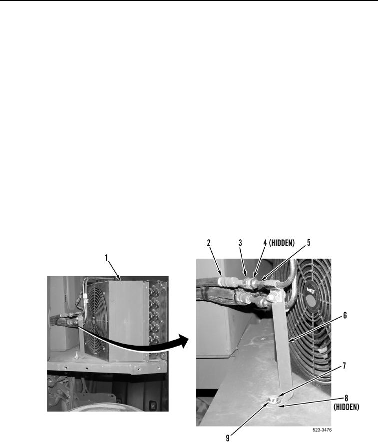
5. Position auxiliary air conditioning condenser (Figure 7, Item 1) on machine.
6. Install bolt (Figure 7, Item 7), two washers (Figure 7, Item 9) and nut (Figure 7, Item 8) on bracket
(Figure 7, Item 6).
7. Install two new O-rings (Figure 7, Item 4), hoses (Figure 7, Item 2), and tube nuts (Figure 7, Item 3) on two
lines (Figure 7, Item 5).
Figure 7. Auxiliary Air Conditioning Condenser Hoses.
0419