
TM 5-2420-231-23-1
0011
Table 1. Hard Start in Cold Temperatures (50F or Below) - Continued.
011
MALFUNCTION
TEST OR INSPECTION
CORRECTIVE ACTION
Test Step 6. Test Grid Heater Coolant
Hard Start in Cold
Temperature Sensor and Circuits.
Temperatures (50F or
Below) - Continued
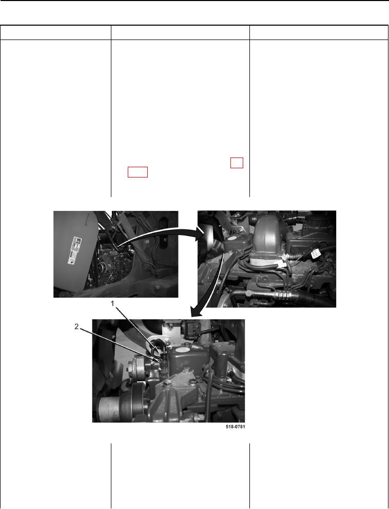
1. Disconnect main chassis sensor
wiring harness connector (Figure
11, Item 1) from grid heater cool-
ant temperature sensor (Figure 11,
Item 2).
2. Connect batteries (WP 0157) and
turn ignition switch to the on posi-
tion (TM 5-2420-231-10).
3. Using a digital multimeter, mea-
Voltage 4.5 to 5.5 Volts - Proceed to
sure voltage between main chas-
step 9.
sis wiring harness connector (WP
Voltage Less Than 4.5 Volts - Proceed
0007, Figure 9) terminal B and
to step 4.
machine ground. Voltage should
be 4.5 to 5.5 volts.
Figure 11. Grid Heater Coolant Temperature Sensor.
0011
4. Turn ignition switch to the off posi-
tion (TM 5-2420-231-10) and dis-
connect batteries (WP 0157).