
TM 5-2420-231-23-1
0011
Table 1. Hard Start in Cold Temperatures (50F or Below) - Continued.
011
MALFUNCTION
TEST OR INSPECTION
CORRECTIVE ACTION
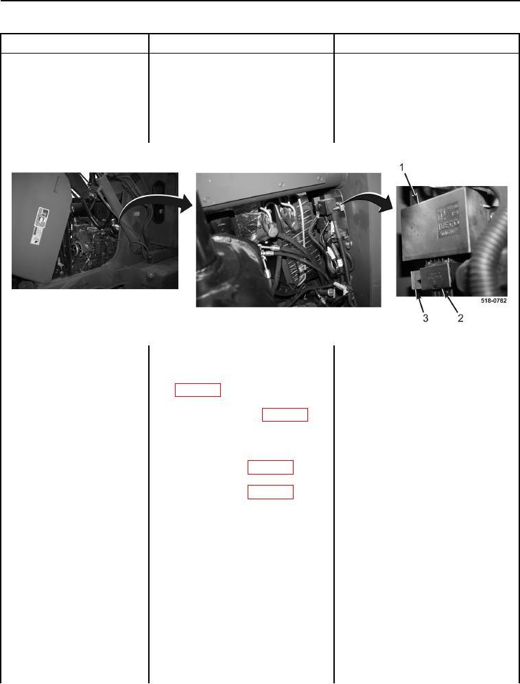
5. Pull red lock lever (Figure 12, Item
Hard Start in Cold
3) outward toward rear of machine
Temperatures (50F or
while slightly pulling downward on
Below) - Continued
heater grid controller wiring har-
ness connector (Figure 12, Item 2)
to disconnect it from heater grid
controller (Figure 12, Item 1).
Figure 12. Heater Grid Controller.
0011
6. Using a digital multimeter, mea-
Resistance 5.0 Ohms or Less -
sure resistance between main
Proceed to Test Step 7.
chassis wiring harness connector
Resistance Greater Than 5.0 Ohms -
(WP 0007, Figure 9) terminal B
Grid heater coolant temperature sensor
and heater grid controller wiring
signal circuit is open.
harness connector (WP 0007, Fig-
Proceed to step 7.
ure 11) terminal 10. Resistance
should be 5.0 ohms or less.
7. Disconnect grid heater wiring har-
ness connector (WP 0007, Figure
15) from main chassis wiring har-
ness connector (WP 0007, Figure
16) (WP 0161).