
TM 5-2420-231-23-1
0013
Table 1. Engine Does Not Crank or Cranks Slowly - Continued.
013
MALFUNCTION
TEST OR INSPECTION
CORRECTIVE ACTION
3. With an assistant, using a digital
Voltage 18 to 26 Volts - Replace
Engine Does Not Crank or
multimeter, measure voltage
starter (WP 0152).
Cranks Slowly - Continued
between main chassis wiring har-
Proceed to Test Step 7.
ness connector terminal 1 and
Voltage Less Than 18 Volts - Proceed
machine ground with ignition
to step 5.
switch in the start position (TM 5-
2420-231-10). Voltage should be
18 to 26 volts.
4. Turn ignition switch to the off posi-
tion (TM 5-2420-231-10).
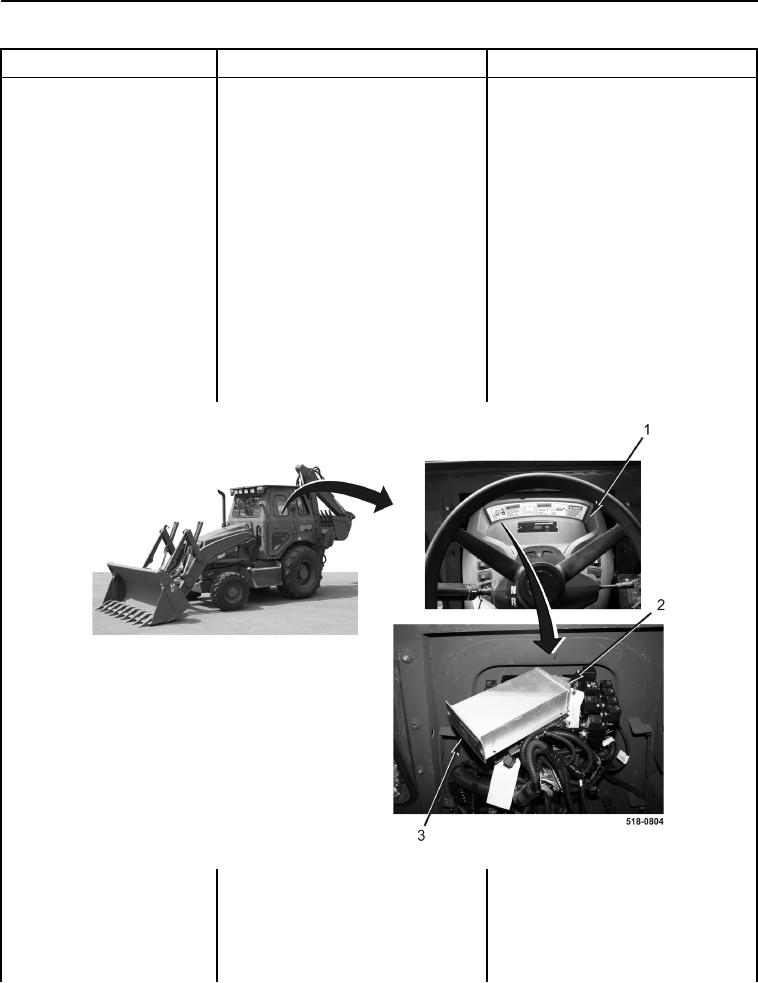
5. Remove instrument panel front
covers (Figure 6, Item 1) (WP
0174).
6. Connect transmission controller
wiring harness connector (Figure
6, Item 2) to transmission control-
ler (Figure 6, Item 3).
Figure 6. Front Console and Transmission Controller.
0013