
TM 5-2420-231-23-1
0013
Table 1. Engine Does Not Crank or Cranks Slowly - Continued.
013
MALFUNCTION
TEST OR INSPECTION
CORRECTIVE ACTION
13. Using a digital multimeter, test for
Continuity - Replace front console
Engine Does Not Crank or
continuity between transmission
wiring harness (WP 0162).
Cranks Slowly - Continued
controller wiring harness connec-
Proceed to Test Step 7.
tor (WP 0007, Figure 20) terminal
No Continuity - Replace transmission
A1 and machine ground. There
controller (WP 0168).
should be no continuity.
Install clutch relay (WP 0007,
Figure 118) on front console wiring
harness.
Install instrument panel front covers
(WP 0174).
Proceed to Test Step 7.
14. Turn ignition switch to the off posi-
tion (TM 5-2420-231-10).
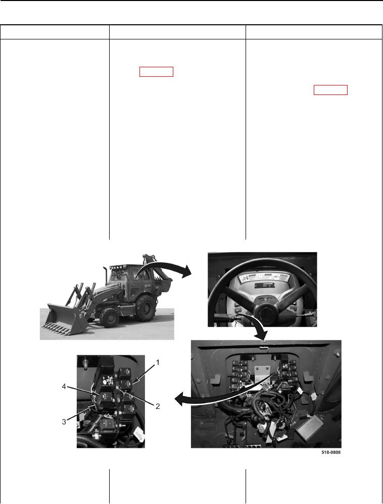
15. Remove neutral relay (Figure 9,
Item 1) from front console wiring
harness connector (Figure 9,
Item 2).
16. Remove shuttle interlock relay
(Figure 9, Item 4) from front con-
sole wiring harness connector
(Figure 9, Item 3).
Figure 9. Shuttle Interlock Relay and Neutral Relay.
0013