
TM 5-2420-231-23-1
0083
Table 1. Ride Control Does Not Operate Correctly - Continued.
083
MALFUNCTION
TEST OR INSPECTION
CORRECTIVE ACTION
Test Step 2. Test for Faulty Ride
Ride Control Does Not
Control Fuse.
Operate Correctly -
Continued
1. Turn ignition switch to the off posi-
tion (TM 5-2420-231-10) and dis-
connect batteries (WP 0157).
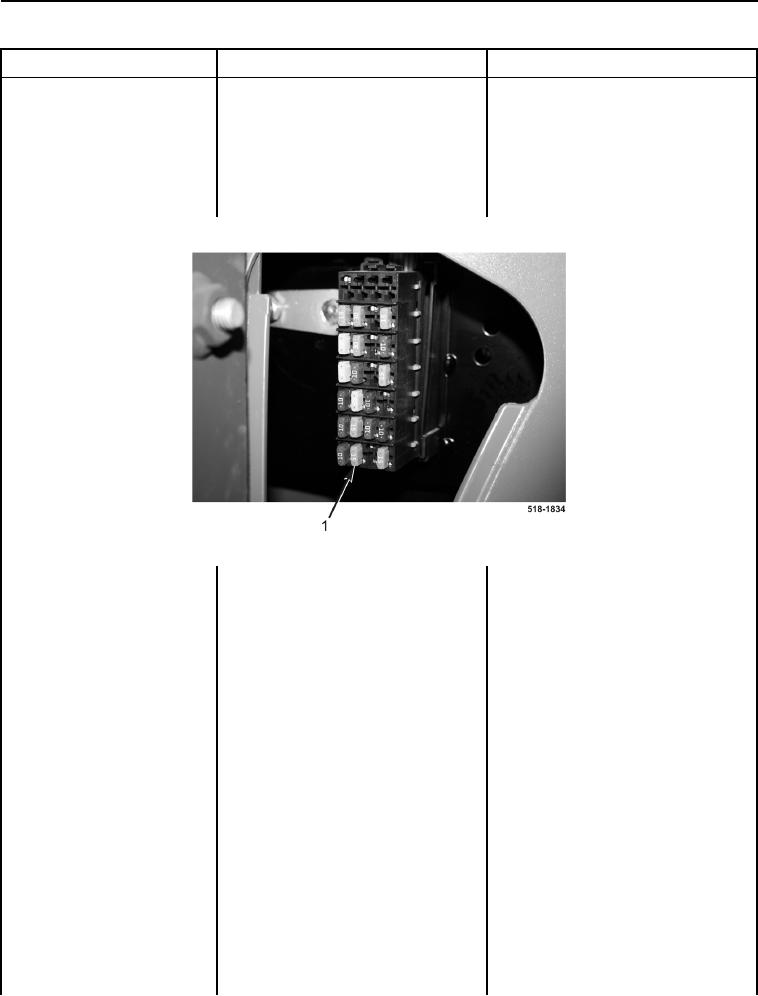
2. Remove ride control fuse (Figure
3, Item 1) (TM 5-2420-231-10).
Figure 3. Fuse Panel.
0083
Resistance 5 Ohms or Less - Install
3. Using a digital multimeter, mea-
ride control fuse (TM 5-2420-231-10).
sure resistance between terminals
Proceed to Test Step 3.
of ride control fuse. Resistance
should be 5 ohms or less.
Resistance Greater Than 5 Ohms -
Proceed to Test Step 7.
Test Step 3. Test for Faulty Ride
Control Switch.
1. Remove two screws (Figure 4,
Item 2) from bezel (Figure 4, Item
1), and pull bezel (Figure 4, Item 1)
away from instrument panel right-
side cover (Figure 4, Item 3).