
TM 5-2420-231-23-1
0083
Table 1. Ride Control Does Not Operate Correctly - Continued.
083
MALFUNCTION
TEST OR INSPECTION
CORRECTIVE ACTION
Ride Control Does Not
Operate Correctly -
Continued
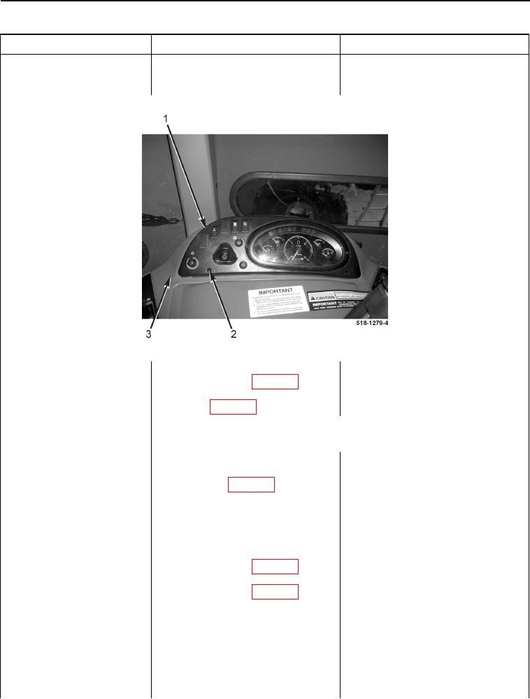
Figure 4. Blower Fan Switch and Bezel.
0083
2. Disconnect side options wiring har-
ness connector (WP 0007, Figure
196) from ride control switch con-
nector (WP 0007, Figure 197).
NOTE
Ensure ride control switch is in the on position (TM 5-2420-231-10).
3. Using a digital multimeter, mea-
Resistance 5 Ohms or Less - Proceed
sure resistance between ride con-
to Test Step 4.
trol switch (WP 0007, Figure 197)
Resistance Greater Than 5 Ohms -
terminals 1 and 2. Resistance
Replace ride control switch (WP 0172).
should be 5 ohms or less.
Proceed to Test Step 14.
Test Step 4. Test for Open Side
Options Wiring Harness.
1. Disconnect side options wiring har-
ness connector (WP 0007, Figure
44) from side console wiring har-
ness connector (WP 0007, Figure
45).
2. Connect batteries (WP 0157) and
turn ignition switch to the on posi-
tion (TM 5-2420-231-10).