
TM 5-2420-231-23-1
0086
FLOWMETER CONNECTION AND FLOW REGULATOR PRESSURE TEST CONTINUED
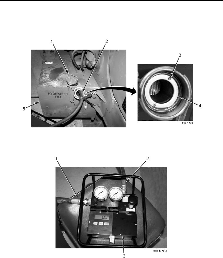
8. Remove two screws (Figure 4, Item 3) and screen (Figure 4, Item 4) from hydraulic reservoir (Figure 4, Item 5).
9. Insert outlet hose (Figure 4, Item 2) until it touches bottom of hydraulic reservoir (Figure 4, Item 5) and secure
hose in place.
Figure 4. Hydraulic Reservoir.
0086
10. Connect inlet hose (Figure 5, Item 1) and outlet hose (Figure 5, Item 2) to flowmeter (Figure 5, Item 3).
Figure 5. Flowmeter Connections.
0086