TM 5-2420-231-23-1
0086
LOADER RELIEF TEST CONTINUED
NOTE
"Dead head" means to continue to apply hydraulic pressure by holding the joystick in the
position for the required action. Release the joystick after the pressure reading has been
recorded.
10. Ensure load valve (Figure 11, Item 2) is fully closed by turning clockwise.
11. Start and run engine at full throttle (TM 5-2420-231-10).
12. Raise loader and hold in raised (dead head) position (TM 5-2420-231-10).
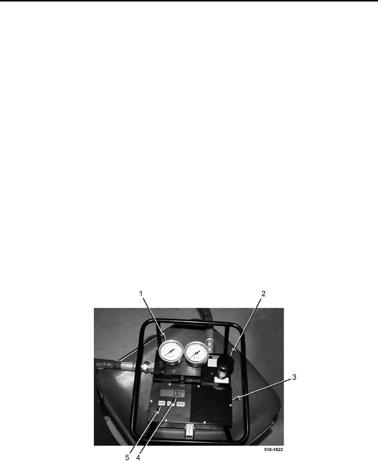
13. Press POWER button (Figure 11, Item 5) to activate flow gauge (Figure 11, Item 4).
14. Slowly open load valve (Figure 11, Item 2) on flowmeter (Figure 11, Item 3) by turning load valve
counterclockwise until load valve is fully open.
15. Slowly close load valve (Figure 11, Item 2) on flowmeter (Figure 11, Item 3) while observing the flow gauge
(Figure 11, Item 4).
16. When the flow gauge (Figure 11, Item 4) reading decreases dramatically by several gpm (Lpm), record
pressure of pressure gauge (Figure 11, Item 1) reading on flowmeter checksheet (2a). The pressure gauge
reading when the loader relief valve starts to open should be 2,600 psi (17,926 kPa) or higher. Repeat three
times.
17. Continue to close load valve (Figure 11, Item 2) on flowmeter (Figure 11, Item 3) until flow gauge (Figure 11,
Item 4) reads 0 gpm (Lpm). Record pressure reading on pressure gauge (Figure 11, Item 1) on flowmeter
checksheet (2b). The pressure gauge should read 3,000 to 3,200 psi (20,684 to 22,063 kPa), which is the fully
open pressure of the loader relief valve.
18. If pressure is not within specification, adjust loader relief valve (see Loader Relief Valve in this work package).
If pressure is not within specification and the reading recorded on flowmeter checksheet (2a) is less then 2,600
psi (17,926 kPa), replace loader control valve assembly (WP 0261).
Figure 11. Flowmeter.
0086

