TM 5-2420-231-23-1
0086
BACKHOE LOAD SENSE RELIEF VALVE TEST CONTINUED
10. Start and run engine at full throttle (TM 5-2420-231-10).
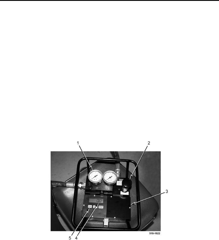
11. Press POWER button (Figure 16, Item 5) to activate flow gauge (Figure 16, Item 4).
12. Fully open load valve (Figure 16, Item 2) on flowmeter (Figure 16, Item 3) by turning counterclockwise.
13. Enable pilot control switch (TM 5-2420-231-10).
14. Curl the backhoe bucket in and hold (dead head) (TM 5-2420-231-10).
15. Slowly close load valve (Figure 16, Item 2) on flowmeter (Figure 16, Item 3) by turning clockwise while
observing the flow gauge (Figure 16, Item 4).
16. When the flow gauge (Figure 16, Item 4) reading decreases dramatically by several gpm (Lpm), record
pressure of pressure gauge (Figure 16, Item 1) on flowmeter checksheet (2c). The flow gauge reading
decreases when the backhoe relief valve just starts to open.
17. Continue to close load valve (Figure 16, Item 2) on flowmeter (Figure 16, Item 3) until flow gauge (Figure 16,
Item 4) reads 0 gpm (Lpm). Record pressure of pressure gauge (Figure 16, Item 1) on flowmeter checksheet
(2d). Pressure gauge should read 3,000 to 3,200 psi (20,684 to 22,063 kPa) which is the full open pressure of
the backhoe relief valve.
18. If pressure is not within specification and or reading recorded on flowmeter checksheet (2c) is less than
2,600 psi (17,926 kPa), replace backhoe control valve assembly (WP 0263).
19. Decrease engine speed to idle (TM 5-2420-231-10).
20. Return backhoe bucket to level (TM 5-2420-231-10).
21. Lower backhoe bucket to ground and turn machine off (TM 5-2420-231-10).
Figure 16. Flowmeter.
0086
END OF TASK

