
2
TM 5-2420-231-23-2
FIELD MAINTENANCE
-
VALVE COVERS REPLACEMENT
0112
Removal, Cleaning and Inspection, Installation
INITIAL SETUP
Tools and Special Tools
References - Continued
Tool Kit, General Mechanic's
WP 0374 (Group Number 0116)
0
0
(WP 0376, Item 117)
Equipment Conditions
Materials/Parts
Intake manifold removed (WP 0114)
0
Rag, Wiping (WP 0375, Item 25)
Engine breather and filter removed (WP 0110)
0
0
Gasket (8)
0
Estimated Time to Complete
References
2.4 hr
0
WP 0369
0
REMOVAL
0112
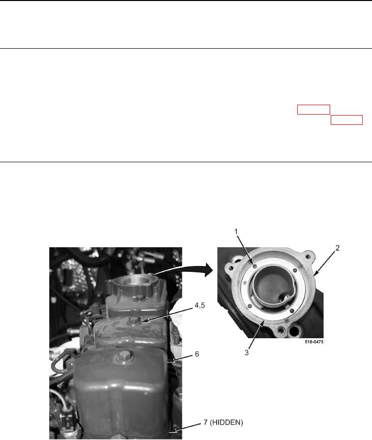
1. Remove four screws (Figure 1, Item 1) and baffle (Figure 1, Item 3) from cover assembly (Figure 1, Item 2).
2. Remove four bolts (Figure 1, Item 4), gaskets (Figure 1, Item 5), two valve covers (Figure 1, Item 6), cover
assembly (Figure 1, Item 2), and four gaskets (Figure 1, Item 7) from machine. Discard gaskets.
Figure 1. Valve Cover.
0112
END OF TASK