
TM 5-2420-231-23-2
0113
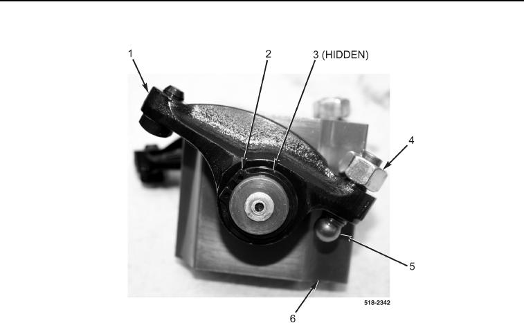
DISASSEMBLY CONTINUED
000113
Figure 2. Rocker Assembly.
0113
END OF TASK
CLEANING AND INSPECTION
0113
Clean and inspect all parts IAW Mechanical General Maintenance Instructions (WP 0369).
END OF TASK
ASSEMBLY
0113
NOTE
The procedure for rocker arm disassembly and assembly is identical for all rocker arm
assemblies. One rocker arm assembly is shown in this procedure.
1. Install two adjuster screws (Figure 2, Item 5) and jamnuts (Figure 2, Item 4) on rockers (Figure 2, Item 1).
2. Install two rockers (Figure 2, Item 1), washers (Figure 2, Item 3), and retaining rings (Figure 2, Item 2) on sup-
port (Figure 2, Item 6).
END OF TASK