
TM 5-2420-231-23-2
0113
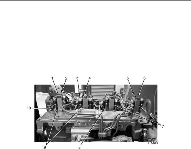
REMOVAL
0113
1. Loosen eight valve adjustment screw jamnuts (Figure 1, Item 4).
2. Loosen eight valve adjustment screws (Figure 1, Item 3).
CAUTION
Tag and mark rocker arm assemblies prior to removal to aid in installation. Failure to follow
this caution may result in severe engine damage or failure.
3. Remove two bolts (Figure 1, Item 2), bolts (Figure 1, Item 1), rocker arm assemblies (Figure 1, Item 9), and
four pushrods (Figure 1, Item 10) from engine.
4. Remove two bolts (Figure 1, Item 5), bolts (Figure 1, Item 6), rocker arm assemblies (Figure 1, Item 7), and
four pushrods (Figure 1, Item 8) from engine.
Figure 1. Rocker Arm Assembly Removal.
0113
END OF TASK
DISASSEMBLY
0113
NOTE
The procedure for rocker arm disassembly and assembly is identical for all rocker arm
assemblies. One rocker arm assembly is shown in this procedure.
1. Remove two retaining rings (Figure 2, Item 2), washers (Figure 2, Item 3), and rockers (Figure 2, Item 1) from
support (Figure 2, Item 6).
2. Remove two jamnuts (Figure 2, Item 4) and adjuster screws (Figure 2, Item 5) from rockers (Figure 2, Item 1).