
TM 5-2420-231-23-2
0113
INSTALLATION
0113
CAUTION
Ensure pushrod tips are properly seated in lifters prior to installing rocker arm assemblies.
Ensure rocker arm tips are properly seated in pushrods prior to tightening rocker arm
assemblies.
Ensure rocker arm assemblies are fully seated in cylinder head prior to tightening bolts.
Failure to follow these cautions may result in severe engine damage or failure.
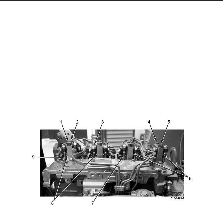
1. Install four pushrods (Figure 3, Item 7), two rocker arm assemblies (Figure 3, Item 6), bolts (Figure 3, Item 5),
and bolts (Figure 3, Item 4) on engine. Tighten four bolts (Figure 3, Item 5) to 32 lb-ft (43 Nm) and four bolts
(Figure 3, Item 4) to 20 lb-ft (24 Nm).
2. Install four pushrods (Figure 3, Item 9), two rocker arm assemblies (Figure 3, Item 8), bolts (Figure 3, Item 1),
and bolts (Figure 3, Item 2) on engine. Tighten four bolts (Figure 3, Item 2) to 32 lb-ft (43 Nm) and four bolts
(Figure 3, Item 1) to 20 lb-ft (24 Nm).
3. Tighten eight valve adjustment screws (Figure 3, Item 3) finger-tight.
4. Perform valve adjustment.
Figure 3. Rocker Arm Assembly Installation.
0113
END OF TASK