
2
TM 5-2420-231-23-2
FIELD MAINTENANCE
-
EXHAUST MANIFOLD REPLACEMENT
0116
Removal, Cleaning and Inspection, Installation
INITIAL SETUP
References
Tools and Special Tools
Tool Kit, General Mechanic's
WP 0369
0
0
(WP 0376, Item 117)
WP 0374 (Group Number 0119)
0
Wrench, Torque, 3/8" Dr., 10-100 ft-lb
0
Equipment Conditions
(WP 0376, Item 146)
Turbocharger assembly removed (WP 0119)
0
Materials/Parts
Estimated Time to Complete
Rag, Wiping (WP 0375, Item 25)
0
4.7 hr
Gasket (4)
0
0
REMOVAL
0116
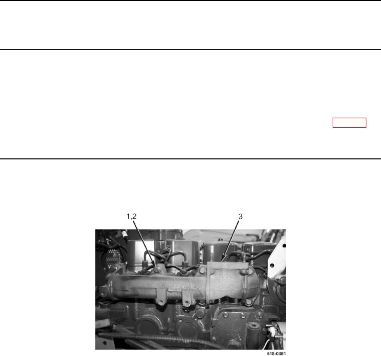
Remove eight bolts (Figure 1, Item 1), four gaskets (Figure 1, Item 2), and exhaust manifold (Figure 1, Item 3) from
engine. Discard gaskets.
Figure 1. Exhaust Manifold.
0116
END OF TASK
CLEANING AND INSPECTION
0116
Clean and inspect all parts IAW Mechanical General Maintenance Instructions (WP 0369).
END OF TASK