
TM 5-2420-231-23-2
0114
INSTALLATION
0114
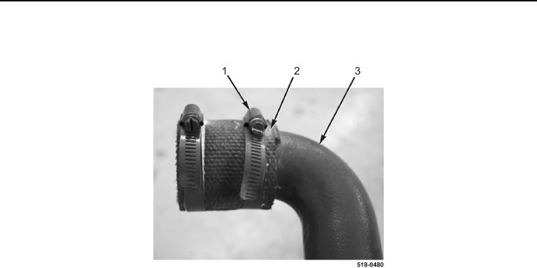
1. Connect sleeve (Figure 5, Item 2) to intake manifold (Figure 5, Item 3) and tighten clamp (Figure 5, Item 1).
Figure 5. Sleeve.
0114
NOTE
Install grid heater in position and orientation as noted in removal.
2. Install grid heater (Figure 6, Item 8) and two new gaskets (Figure 6, Item 3) on air intake cover
(Figure 6, Item 10).
NOTE
Install wires as noted in removal.
3. Install cable (Figure 6, Item 7), two wiring harness eyelets (Figure 6, Items 9 and 5), washer (Figure 6, Item 2),
and three nuts (Figure 6, Items 6, 4, and 1) on grid heater (Figure 6, Item 8).