
TM 5-2420-231-23-2
0136
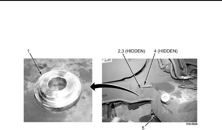
FUEL TANK INSTALLATION CONTINUED
3. Install spacer (Figure 7, Item 1), fuel tank (Figure 7, Item 5), spacer (Figure 7, Item 4), two washers (Figure 7,
Item 3), and bolts (Figure 7, Item 2) on machine.
4. Tighten two bolts (Figure 6, Item 1).
5. Remove suitable lifting device (Figure 6, Item 3) from fuel tank (Figure 6, Item 4).
Figure 7. Spacer.
0136