
TM 5-2420-231-23-2
0136
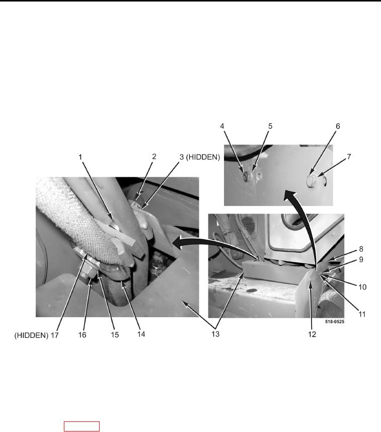
FUEL TANK COVER AND PLATE INSTALLATION
0136
1. Install cover plate (Figure 9, Item 8), washer (Figure 9, Item 7), bolt (Figure 9, Item 6), and nut (Figure 9,
Item 12) on machine.
2. Install washer (Figure 9, Item 5), bolt (Figure 9, Item 4), washer (Figure 9, Item 10), and nut (Figure 9, Item 9)
on cover plate (Figure 9, Item 8).
3. Install cover (Figure 9, Item 13), two spacers (Figure 9, Items 1 and 17), three clamps (Figure 9, Item 14),
washer (Figure 9, Item 3), bolt (Figure 9, Item 2), new lockwasher (Figure 9, Item 15), and nut (Figure 9,
Item 16) on machine.
4. Install bolt (Figure 9, Item 11) on cover (Figure 9, Item 13).
Figure 9. Fuel Tank Cover and Plate.
0136
5. Refill fuel tank (TM 5-2420-231-10).
END OF TASK
FOLLOW-ON TASKS
0136
Connect batteries (WP 0157).
END OF TASK
END OF WORK PACKAGE
0136-9/(10 blank)