
TM 5-2420-231-23-2
0136
FUEL TANK INSTALLATION CONTINUED
NOTE
Install lines as tagged and marked during removal.
Remove plugs and caps from hoses and fittings.
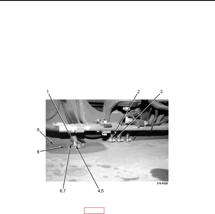
6. Connect three hoses (Figure 8, Item 2) and tighten clamps (Figure 8, Item 3) on fuel tank (Figure 8, Item 9).
NOTE
Install wires as tagged and marked during removal.
7. Install two wires (Figure 8, Items 5 and 7), new locknuts (Figure 8, Items 4 and 6), and position cap (Figure 8,
Item 1) on fuel tank sending unit (Figure 8, Item 8).
Figure 8. Hoses.
0136
8. Install left-rear wheel and tire assembly (WP 0217).
END OF TASK