
TM 5-2420-231-23-2
0139
REMOVAL
0139
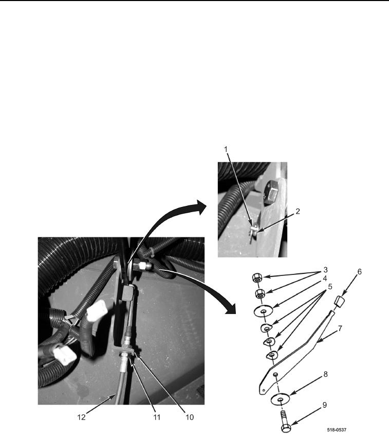
1. Loosen two jamnuts (Figure 1, Item 11) on cable (Figure 1, Item 12).
2. Remove cotter pin (Figure 1, Item 1), washer (Figure 1, Item 2), and cable (Figure 1, Item 12) from lever
(Figure 1, Item 7) and bracket (Figure 1, Item 10). Discard cotter pin.
NOTE
Note position and orientation of lever and washers to aid in installation.
3. Remove two nuts (Figure 1, Item 3), washer (Figure 1, Item 4), three spring tension washers (Figure 1, Item 5),
lever (Figure 1, Item 7), washer (Figure 1, Item 8), and bolt (Figure 1, Item 9) from machine.
4. Remove knob (Figure 1, Item 6) from lever (Figure 1, Item 7).
Figure 1. Hand Throttle Assembly.
0139
END OF TASK