
TM 5-2420-231-23-2
0162
INSTALLATION CONTINUED
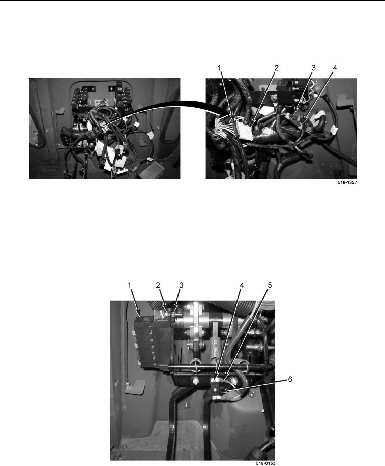
15. Connect front console wiring harness (Figure 10, Item 3) to front console options wiring harness
(Figure 10, Item 4).
16. Connect front console wiring harness (Figure 10, Item 1) to powershift wiring harness (Figure 10, Item 2).
Figure 10. Powershift and Front Console Options Wiring Harness Connection.
0162
NOTE
Install wires as tagged and marked during removal.
17. Connect two front console wiring harness connectors (Figure 11, Item 5) to brake switch (Figure 11, Item 6)
and install two screws (Figure 11, Item 4).
18. Install fuse block (Figure 11, Item 1), bolt (Figure 11, Item 2), and new locknut (Figure 11, Item 3) on machine.
Figure 11. Fuse Block.
0162
END OF TASK