
TM 5-2420-231-23-2
0162
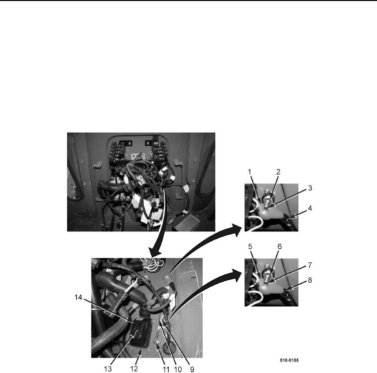
REMOVAL CONTINUED
6. Loosen bolt (Figure 4, Item 13) and disconnect front console wiring harness connector (Figure 4, Item 14) from
main chassis wiring harness connector (Figure 4, Item 12).
7. Remove bolt (Figure 4, Item 11), ground eyelet (Figure 4, Item 10), and ground eyelet (Figure 4, Item 9) from
cab.
8. Position two rubber boots (Figure 4, Items 1 and 5) aside.
9. Remove nut (Figure 4, Item 2) and front console wiring harness eyelet (Figure 4, Item 4) from 24-V stud
(Figure 4, Item 3).
10. Remove nut (Figure 4, Item 6) and front console wiring harness eyelet (Figure 4, Item 8) from 12-V stud
(Figure 4, Item 7).
Figure 4. Main Chassis Wiring Harness, Power, and Ground Connections.
0162