
TM 5-2420-231-23-2
0162
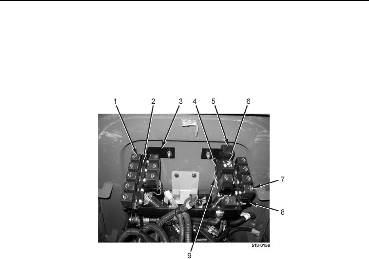
REMOVAL CONTINUED
11. Remove eight relays (Figure 5, Item 1) from relay sockets (Figure 5, Item 2) on left side of bracket
(Figure 6, Item 3).
12. Remove five relays (Figure 5, Item 7) from relay sockets (Figure 5, Item 8) on right side of bracket
(Figure 5, Item 3).
13. Remove hazard relay (Figure 5, Item 5) from relay socket (Figure 5, Item 4).
14. Remove shuttle interlock timing relay (Figure 5, Item 6) from relay socket (Figure 5, Item 9).
Figure 5. Relays.
0162
NOTE
Tag and mark relay sockets to aid in installation.
15. Remove five locknuts (Figure 6, Item 3), bolts (Figure 6, Item 2), and eight relay sockets (Figure 6, Item 1) from
machine. Discard locknuts.
16. Remove four locknuts (Figure 6, Item 6), bolts (Figure 6, Item 5), and seven relay sockets (Figure 6, Item 4)
from machine. Discard locknuts.
NOTE
Note location and quantity of tiedown straps to aid in installation.
17. Remove tiedown straps (Figure 6, Item 7) from front console wiring harness (Figure 6, Item 8). Discard
tiedown straps.
NOTE
Note routing of wiring harness to aid in installation.
18. Remove front console wiring harness (Figure 6, Item 8) from machine.