
TM 5-2420-231-23-2
0166
INSTALLATION CONTINUED
NOTE
Install wires as tagged and marked during removal.
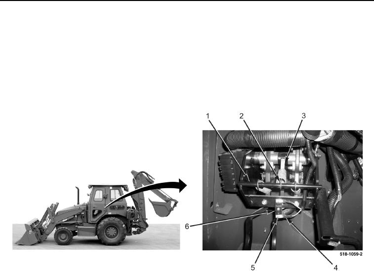
3. Install two wires (Figure 3, Item 4) and screws (Figure 3, Item 5) on brake light switch (Figure 3, Item 6).
4. Rotate brake lamp lever (Figure 3, Item 3) toward rod (Figure 3, Item 1).
5. Connect spring (Figure 3, Item 2) to rod (Figure 3, Item 1).
Figure 3. Brake Light Switch Wires.
0166
END OF TASK