
TM 5-2420-231-23-2
0190
REMOVAL CONTINUED
NOTE
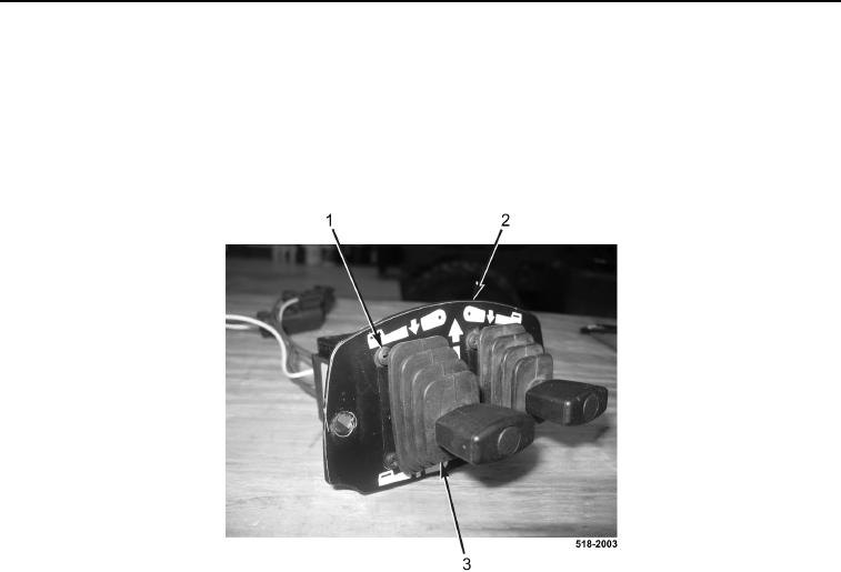
Note position and orientation of stabilizer control switches to aid in installation.
5. Remove eight screws (Figure 3, Item 1) and two stabilizer control switches (Figure 3, Item 3) from plate
(Figure 3, Item 2).
Figure 3. Plate.
0190
END OF TASK
CLEANING AND INSPECTION
0190
1. Clean and inspect all parts IAW Mechanical General Maintenance Instructions (WP 0369).
2. Clean and inspect all parts IAW Electrical General Maintenance Instructions (WP 0370).
END OF TASK
INSTALLATION
0190
NOTE
Install stabilizer control switches in position and orientation noted during removal.
1. Install two stabilizer control switches (Figure 3, Item 3), and eight screws (Figure 3, Item 1) on plate
(Figure 3, Item 2).