
2
TM 5-2420-231-23-2
FIELD MAINTENANCE
-
PILOT CONTROLS CONTROLLER REPLACEMENT
01
91
Removal, Cleaning and Inspection, Installation
INITIAL SETUP
References - Continued
Tools and Special Tools
Tool Kit, General Mechanic's
WP 0370
0
0
(WP 0376, Item 117)
WP 0374 (Group Number 0316)
0
Materials/Parts
Equipment Conditions
Rag, Wiping (WP 0375, Item 25)
Machine parked (TM 5-2420-231-10)
0
0
Tag, Marker (WP 0375, Item 33)
Batteries disconnected (WP 0157)
0
0
References
Estimated Time to Complete
WP 0369
0.3 hr
0
0
REMOVAL
0191
NOTE
Tag and mark wires to aid in installation.
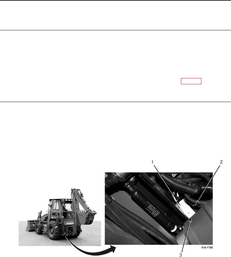
1. Disconnect electrical connector (Figure 1, Item 2) from pilot control module (Figure 1, Item 3).
2. Remove two mounting screws (Figure 1, Item 1) and pilot control module (Figure 1, Item 3) from machine.
Figure 1. Pilot Control Module.
0191
END OF TASK